Tuesday, August 26, 2008

Show Bearing & Non-bearing Walls

This post addresses a question I have had many clients ask me as they begin to develop their documents in Revit. In CAD many firms develop different lineweight or colour representations for the Bearing and Non-bearing elements they are documenting. Revit does define structural usage parameters within each element but this does not affect the visual display of these objects. To do this we have to use the filters tool in the visibility graphics.


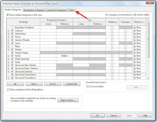
First: We open the visibility graphics in the view we want to show the bearing and non-bearing elements.


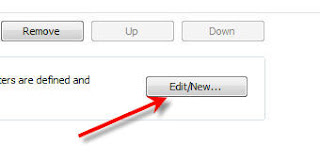
Second: We select the Filters tab and open this portion of the window. Then select the Edit/New button to open the Filters dialogue box.


Third: We define two new filters. By selecting the new filters button. Name one Bearing and the other Non-Bearing to easily identify later.


This is where we begin to use some of Revit's fantastic categorizations. After all it is BIM and all the info is properly organized. We choose from the categories list to define specifically what we are filtering. Choose the Walls category, then on the right define the filter rule to be "structural usage".


The key here, is the defining the proper "equals" definition below the filter rule. If you are defining the "Bearing" filter then choose the Bearing from the equals menu, and vice versa for the "Non-bearing" filter.


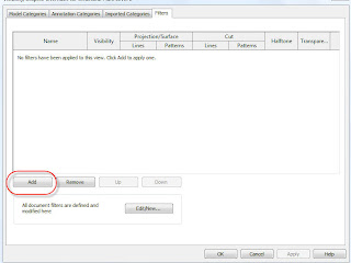
Ok, we are almost done. Hit the OK button to accept the settings, which will take you back to the V/G(visibility graphics) dialogue box. Now all you have to is ADD the new filters created to this view.(notice how i said "this" view.) These filters are defined per view basis, just as all the definitions for the V/G are per view basis. Adding the filters to other views is very easy since you just created the filters.....anyway I digress..


Select the ADD button in the V/G view. Then you will see the names of the two filters created in the add filters dialogue box. Select them , then hit OK.


Now, you will see the filters listed in the view, so really its just a matter of defining how you want to display your Bearing & Non-bearing elements. Use the override tools to redefine the appearance of these elements(remember, projection or cut lines will show changes on the elements depending on where the elements are displayed in relation to your view range). Change the line weight or pattern displayed for the elements.


Once you have defined the changes to the filters, all you have to do is add some walls to your view. Select the "Structural wall" tool and these walls will appear as you defined "Bearing" walls to appear. Select the Architectural "Wall" tool and these walls will appear as you defined the "Non-bearing walls. (Each wall has a parameter that defines whether its bearing or non-bearing)


Now you can quickly display these elements the way you want. With Revit, life is good!!

If you have any questions related to this topic or any other related topics, refer to my e-mail link, and I'll try and help. Cheers.

Monday, August 18, 2008

Creating an AXONOMETRIC VIEW-REVIT


With all the great things that Revit has to offer, creating views is one its most powerful tools. We use all the views for our documentation, but sometimes Revit provides tools that give us the ability to kick it up a notch. Axonometric views are nothing new to designs, but the ability to create them is usually limited to those with time and patience(something we usually don't have enough of). Revit uses Sections and referencing tools that allows for these type of views to be created seamlessly. I am a visual learner which is why anything with a video is always good for me. Have a look at this AVI and you too can create an axonometric view that will WOW, any Revit non believer. I know the video is small, but the key here is:

  1. Copying the default 3D view and renaming it to Axonometric view
  2. Create a new Section of the building: Rename to Axo-section
  3. Go to the New 3D view.(Make sure you click an empty space in the view window)
  4. Select from View pulldown menu the "Orient" tool then "Orient to View"
  5. This is where you select the Section created "Axo-section"
  6. Once in the new view you can orbit as if in 3D perspective
  7. Voila!!!!!! Axonometric Section.


Thursday, August 14, 2008

Converting the PCP to CTB

CONVERTING PCP REVIT FILES TO AUTOCAD CTB FILES

Anyone that has taken the leap from the 2D CAD world to the 3D Revit platforms has undoubtedly seen the great benefits that come from using BIM(Buiding Information Modelling) software. Parametrics, Bi-directional association, highly coordinated documentation, the list goes on.
Since converting to any new software can be hard due to the learning curve involved; Revit mitigates this process by allowing files to be exported to DWG format at any point of the design. This capability is very powerfull when releasing documentations to consultants that may not be on the Revit platform but still require the designers to provide key documentation. One great feature of this export functionality is the ability to carry over the plot definitions that Revit applies to its families into a CTB file for use in AutoCAD.
The process is simple:
First take an existing Revit file and export out to CAD using the CAD standards format. Then when exporting out, you will notice that a PCP file is created with the same file name as the one used to export out. This PCP file is the Plotting Configuration that Revit uses. Now we must convert this PCP to a newer plot configuration like CTB.
Open your CAD software and using the Plot Style Table configuration you must define a new name from the pull down list given. At this point AutoCAD will prompt to choose whether you would like to create one from scratch, use a CGF file, or a PCP or PC2 file. Choose PCP selection and then browse to the directory where the export was done. Then define the name of the Configuration and finish.
You will now be able to use the Revit plot configurations for all layers used in the current drawing based on the Revit lineweight.
Now you can not only send those files to consultants but they can be plotted in the same great way that Revit prints any view, that is if your feel nice and want to give them the CTB file as well.