First: We open the visibility graphics in the view we want to show the bearing and non-bearing elements.
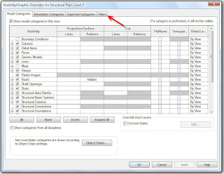

Second: We select the Filters tab and open this portion of the window. Then select the Edit/New button to open the Filters dialogue box.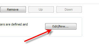

Third: We define two new filters. By selecting the new filters button. Name one Bearing and the other Non-Bearing to easily identify later.


This is where we begin to use some of Revit's fantastic categorizations. After all it is BIM and all the info is properly organized. We choose from the categories list to define specifically what we are filtering. Choose the Walls category, then on the right define the filter rule to be "structural usage".

The key here, is the defining the proper "equals" definition below the filter rule. If you are defining the "Bearing" filter then choose the Bearing from the equals menu, and vice versa for the "Non-bearing" filter.
Ok, we are almost done. Hit the OK button to accept the settings, which will take you back to the V/G(visibility graphics) dialogue box. Now all you have to is ADD the new filters created to this view.(notice how i said "this" view.) These filters are defined per view basis, just as all the definitions for the V/G are per view basis. Adding the filters to other views is very easy since you just created the filters.....anyway I digress..
Select the ADD button in the V/G view. Then you will see the names of the two filters created in the add filters dialogue box. Select them , then hit OK.

Now, you will see the filters listed in the view, so really its just a matter of defining how you want to display your Bearing & Non-bearing elements. Use the override tools to redefine the appearance of these elements(remember, projection or cut lines will show changes on the elements depending on where the elements are displayed in relation to your view range). Change the line weight or pattern displayed for the elements.


Once you have defined the changes to the filters, all you have to do is add some walls to your view. Select the "Structural wall" tool and these walls will appear as you defined "Bearing" walls to appear. Select the Architectural "Wall" tool and these walls will appear as you defined the "Non-bearing walls. (Each wall has a parameter that defines whether its bearing or non-bearing)

Now you can quickly display these elements the way you want. With Revit, life is good!!
If you have any questions related to this topic or any other related topics, refer to my e-mail link, and I'll try and help. Cheers.